
8 min read
Reconstructing the Balclutha
We rebuilt an 1886 ship in 3D from its original drawings.
We took the original drawings of a ship built in 1886 and rebuilt it as a 3D model where you can open in a browser, pull apart, and put back together. You can click on any piece and see which drawing it came from.
The research question
Can a historical ship record become a vessel that people can inspect, take apart, reassemble, challenge, and correct without turning gaps in the record into false certainty?
That question led to several smaller ones:
Can we keep the source drawing separate from our interpretation, the generated geometry, and the review decision from naval architects?
Can a person trace any visible part back to its evidence and see what remains uncertain?
Can the vessel be decomposed and recomposed without losing identities or relationships?
Can the system stop safely when a file, unit, source, or claim is unsupported?
Can another researcher reproduce the bounded result from a clean starting point?
Why an 1886 ship proves something about a modern ship
The obvious question about this research case is what a Victorian sailing ship has to do with a tanker in drydock next quarter.
The answer is that the hard part of reconstruction is not the era of the vessel. It is the state of the record. Balclutha's record has exactly the properties that make a modern in-service ship difficult: drawings produced by different hands at different times, later modifications that were never fully documented, surveys taken decades apart that do not describe the same physical reference, and regions where the sources simply run out.
Those are the same conditions a 20-year-old commercial vessel presents. Working from a historical record also let us test the pipeline against a rich, complete, publicly available source set, and publish the result openly, which we could not do with a customer's fleet.
What Balclutha demonstrates is therefore transferable: that a legacy 2D drawing set can become a structured, decomposable 3D model, and that the parts the drawings do not support can stay visible as open questions.
Why The Balclutha

Balclutha is a three-masted steel sailing cargo ship built in 1886. She is complex, historically significant, and very well documented.
The survey held by the Library of Congress contains 71 measured drawings and 240 pages of written records, plus photographs. It was produced by the Historic American Engineering Record, a U.S. government programme that documents historic structures in detail.
That gave us drawings covering the whole ship rather than one isolated part: the hull, the decks, the structure inside, the openings, the fittings, and the rigging. It also gave us the contradictions and missing details that any real project has.
What we worked from
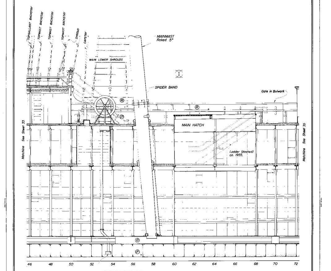
We used those 71 drawings and 240 pages, and listed every one of them up front.
The important thing is that these records do not all describe the same ship.
The vessel changed over the decades, and the records were made at different moments:
When | What it is |
|---|---|
1886 | When she was built |
1988 | The full measured survey. The most complete record, so we used it as the main version |
1998 | A survey of the left-hand side only, taken with a surveying instrument |
2020 | A laser scan of the hull |
We keep these separate rather than blending them together. A 1988 measurement and a 2020 scan can both be correct and still disagree, because the ship changed in between. Averaging them would produce a confident number describing a ship that never existed.
What we reconstructed
The finished model covers four parts of the ship:
The hull, the outer shape of the vessel.
The structure inside it: decks, bulkheads, framing.
Everything above deck: deckhouses, hatches, openings, equipment.
The rigging: masts, spars, and the ropes and wires that hold them.
Here is what we produced:
You can click on 114 separate things. 65 of them are parts of the ship. The other 49 are gaps: places where the drawings ran out and we recorded as a question instead of generating the missing parts.
136 notes record how those things connect to each other, so the model knows which part sits on which.
44 of the 114 have an actual 3D shape you can look at, made up of 307 individual solid pieces.
The remaining 70 have no shape, because we do not know their shape. They are still clickable, and selecting one tells you what we do know and what still needs answering.
The test slice at Frames 60-62
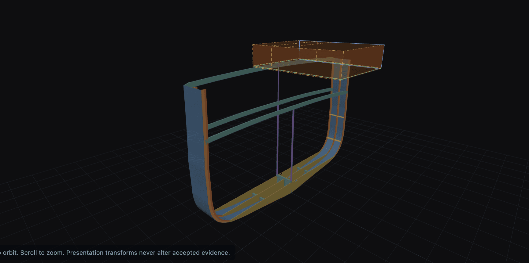
A ship has ribs, numbered from front to back. "Frames 60 to 62" means the section between rib 60 and rib 62: one slice of the ship, near the middle, a couple of metres long.
Rather than attempt the whole vessel at once, we did that one slice first as a
practice run and did it thoroughly. Every piece traced back to the drawing it came from. 32 pieces in total, and 18 notes recording which piece connects to which. Then we pulled it apart and rebuilt it, to confirm nothing was lost on the way.
Once that worked, we built the whole ship and dropped the finished slice into it, without watering it down to match its less-verified surroundings.
What the Workbench proves
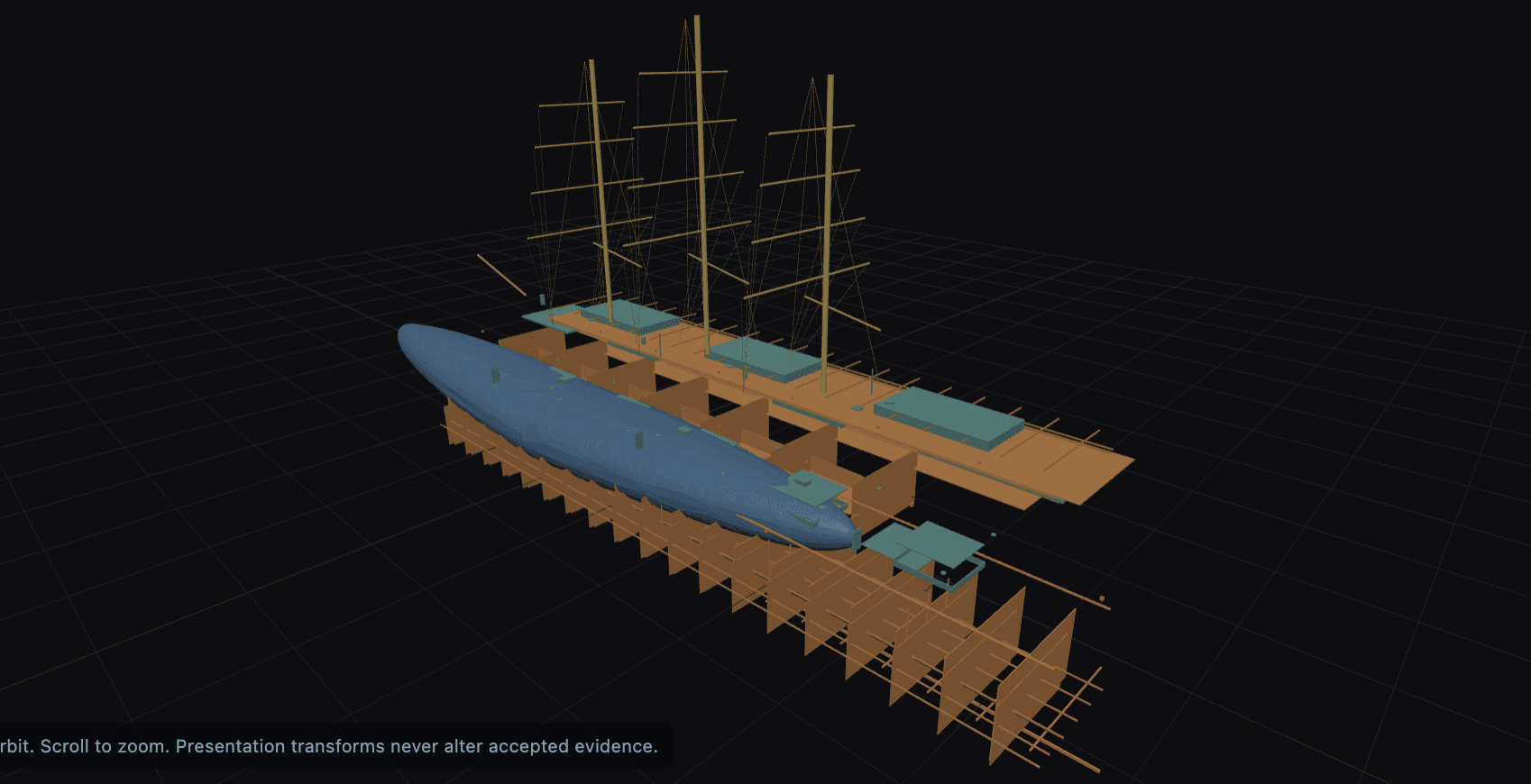
The Workbench proves that a research vessel can be more than a picture, and viewed as an interactive 3D model. A reader can:
browse the complete vessel hierarchy;
select reconstructed geometry or a named unresolved identity;
isolate, hide, and restore parts and families;
inspect cutaway and exploded presentations;
move from vessel to system, assembly, and part;
review evidence state, assumptions, measurements, and correction questions;
recompose the governed inventory without losing its 114 identities or 136 relationships.
How we built confidence in the result
We tested more than whether the vessel looked plausible on screen. Four checks stand behind the result.
We rebuilt the complete vessel in a clean, empty environment from the declared drawings alone, then compared that rebuild against the original in detail. The two matched, which places the result in the recorded process rather than in undocumented manual correction along the way.
We ran both a valid STEP file and a deliberately malformed one. The valid file produced geometry that stayed within its evidence. The malformed file stopped before it could emit geometry, measurements, or downstream work, rather than producing a partial assembly that still reads as finished.
We checked the finished ship against a complete part list. Before assembling the vessel, we listed every component the 71 drawings mention, then verified the assembled model against that list. Every listed part had to end up in one of two states: reconstructed, or carried as a labelled question. Parts that were absent, duplicated, or unclassifiable failed the check, so nothing could silently go missing.
We ran mutation tests against the inputs. Removing a source, corrupting a component’s identity, concealing an omission, stripping a publication approval, and promoting a research result to approved status were each required to fail and stop. Publication approval here is copyright clearance, held item by item, with anything unapproved or ambiguous withheld by default. Approved status is the boundary this vessel does not cross: no engineer has certified it, and the process cannot present it as certified.
This gives collaborators a dependable starting point: the research record is inspectable, its replay is reproducible, every declared part is accounted for, and unsupported changes cannot quietly become accepted engineering output.
What this means for a fleet owner or a shipyard
Forge is built to deliver four things: faster drydock planning, no Class surprises, less office workload, and a trusted record. All four depend on one thing being possible first: that a reliable 3D model can actually be built from the messy records a real ship has. That is the claim this case tests.
Balclutha’s records have the same problems as any working ship’s. 1) The drawings were made by different people at different times. 2) The ship was modified without the drawings being updated. 30 The surveys disagree with each other. Each outcome below points to the part of the finished model that demonstrates it, so none of this is taken on trust.
Faster drydock planning.The reason drydock jobs blow up is that the real condition of the ship is discovered after the hull is opened, when the schedule is already fixed. This model shows the alternative: before any work starts, it already tells you which parts are established and which 49 are unknown. On a paying job, that list of unknowns is the drydock surprise, found during planning instead, while there is still time to order a survey or adjust the scope.
Less office workload. Reconciling the records was the work of this project: 71 drawings and 240 pages of survey notes, cross-referenced into one model, with records from different decades kept separate instead of blended. That cross-referencing is exactly what a technical department does by hand before every planning cycle today. Balclutha shows the system doing it.
No Class surprises. A surveyor’s finding is only a surprise if you did not know the state of your own vessel and its documentation. In this model, every part shows what supports it and every gap is declared. An owner with that picture knows what the surveyor will find before the surveyor arrives.
A trusted record. Nothing in the model is unsourced. Every part traces to the drawing that established it, every gap is admitted rather than papered over, and the four checks above prove the whole thing can be rebuilt and audited. That is what makes the model something you can put in front of a surveyor or a yard, rather than one more document that might be wrong.
One caution: this is a research reconstruction, not certified engineering. Using it for design or fabrication still requires qualified engineers to review and sign it, and Forge keeps that step explicit.
What we are building next
Internal structures and machinery. The hull is only the envelope. Most repair scope lives inside it, in the piping, engines, and the machinery spaces. We are extending the same drawing-to-3D route to those systems.
Hull geometry is continuous and heavily constrained by naval architecture, which gives a reconstruction something to check itself against. Piping has none of that. It is densely packed, and every draughtsman drew it differently. It also gets altered constantly without anyone updating the sheet.
Dead CAD into editable models. Plenty of vessels do have a 3D file. It just cannot be used, either because the format died or because the whole ship arrives as one fused solid with no part boundaries in it. The work here is recovering those boundaries and handing back geometry an engineer can edit.
Back out to 2D.The reverse direction matters as much as the forward one. Fabrication does not run from a model, it runs from drawings. A shop that cannot get a usable drawing out of a system will not adopt the system, whatever the model is worth back in the technical department.
So we are building the return path: sections and part drawings generated from the reconstructed model.